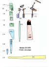
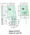
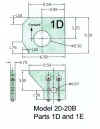
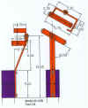
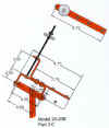
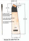
Model 20-20B June 05
These
drawings reflect the evolution of the basic 20-20 design with many
changes to
the detail parts and new features such as provision to swing the
oar out of
the water for protection around docks and reduce growth of
marine plants
and animals.
I have had
many requests for a complete set of drawings that could be used
to build a
model. I think this set will do that.
The only
decisions needed to be made by the builder are the choice of a mounting
scheme
and the length of the oar to fit his boat.
Simple
construction using readily available materials is the basic design goal.
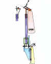 Model 20-20B overall view
The support
frame is plywood and the vane mast support is UV resistant PVC
ridged electrical
conduit.
 Prototype under construction
shown mounted on a
copper tubing frame mount on a
simulated transom.
 A typical mounting frame. This one is of copper tubing
 Prototype mount for this presentation.
 This bit of copper pipe has been mounted in the tide
line in South
Florida for several years and shows no signs of structural
damage other than
the green oxide film.
 Showing oar rotated out of the water for safety
around docks and to
reduce build up of marine growth when
not in use.
 Showing how to laminate the shaft hangers from
Three layers
of plywood. The middle layer is cut away to make
drilling for the support bolts easy. After the epoxy has hardened
a
drill will easily follow the cavity and result in well aligned parts.
A version using
PVC for the shaft and bearings proved to be a
good way to
build and is both easy to make and is quite strong.
The assembly
is a bit tricky at first look but by cutting the slot shown
on the end
caps and using at least 1-1/4 size pipe the crankshaft
and other
parts go together with enough clearance. The caps are
cut to
fit in the photos but need not be made so short.
 The main pivot shaft is the gray PVC pipe and the hangers
are the
same ones in the previous photos that have been cut to fit the
larger
PVC pipe. The bolts go through the cut off fitting and the pipe but
clear
the control shaft. The slot in the end cap will allow it to make the turn
at the
bearing point.
 More
detail
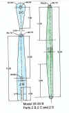
 Assembly of crank shaft parts
The
crankshaft supports can be assembled after the shaft is pre bent by turning
the PVC
caps with their slots to slide past the 90 degree bends.
The
caps are cut to length and drill for a loose fit on the shaft. They are retained
on the
gray PVC pipes with a # 6 x 1/2 self tapping screw.
Notes on building the parts---
The first
decision to be made in building or buying a self-steering device
is how to
mount it on your boat. This design provides for many options.
A simple
plywood platform fastened to the boat's transom or deck or
metal pipes,
extrusions or welding could be used . The copper frame
I show is
quite strong enough. I use type " L " copper fittings and pipe.
Soldered with
ordinary plumbing solder will work. A good water tight
quality joint
is certainly not needed. With the short lengths needed I
find scrap or
used material is a very good way to cut costs.
The
plywood shown is 3/4 inch . Use a good grade of pressure treated pine
or use epoxy
to laminate stock. The oar can be made that way with the
lower part of
the blade being only two layers of 1/4 ply. This can result in an oar
that is as
strong as the wooden props used on light aircraft.
The bent
up metal bar parts are formed from 1/4 x 1.0 extruded aluminum
sold in
building supply or hard ware stores. This material is in the annealed
state
and can be
held in a vise and bent with a large hammer.
The vane mast is PVC. Use rigid electrical conduit for added UV protection.
The vane blade is a light weight 1/4 plywood lightly coated with epoxy resin.
Details will be filled in as I go--- Please contact me if you need help now at
data 17 June 2005
